I am using the latest (version 2.575) Volumio on a Raspberry Pi 3, model B.
I’m successfully using the GPIO ‘buttons’ plugin to give transport controls. In a remote box, 4 momentary push buttons are connected to a 3.3v positive rail from the Pi and pulse respective GPIO pins high to trigger each transport function.
I’ve now installed and would like to use the GPIO ‘control’ plugin to show status, using the same, common 3.3v+ rail to light 2 LEDs, one to show ‘pause’, the other ‘stopped’ state.
With the necessary series resistors limiting their current, I’ve got the LED cathodes connected to GPIO pins 13 & 19.
When I save the settings, both the LEDs light - proving that the pins are taking each cathode low as intended.
However, when you play / pause / stop, the LEDs don’t do what they’re supposed to.
Back in the setup screen, I’ve tried with GPIO pins set to ‘on’ and ‘off’. I’d noticed an example diagram showing different GPIO pins supplying positive to the LED anode and using the fixed ground for the cathode - so I tried wiring this way - but still no good.
So I would be most grateful to hear from anyone who has been able to successfully use the GPIO ‘control’ plugin or from anyone who knows of any operational issues with it.
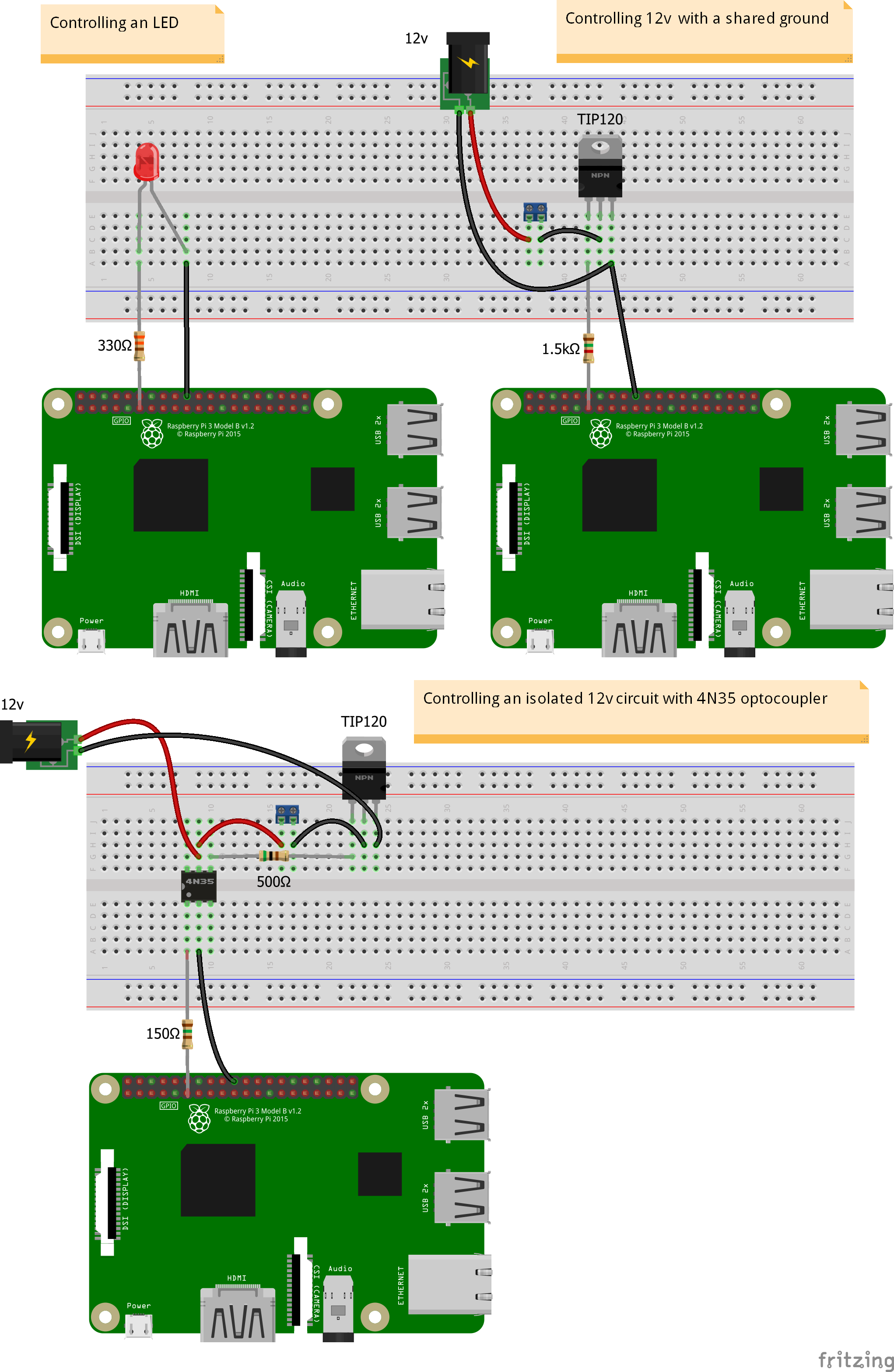
I’m the developer who wrote the plugin. You said you’ve wired the LEDs using a common 3.3v rail. Could you change you wiring so that the Pi is powers your LEDs? That’s how I intended the plugin is intended to work as most of the GPIO are pulled low on startup and generally you want everything turned off until the system tells us there’s music playing. Try connecting each GPIO pin to a resistor and then to the anodes and then back to Pi ground, that should work, like in the schematic below.
It might be worth opening a terminal window and typing
sudo journalctl -f
This will let you see the volumio events being handled and will show you what state the plugin sets them.
Look at the wiring on the top left schematic, that should give you a good idea of what to do.
Thanks very much for your reply and for inventing the useful plug-in.
Before writing my post I did see your diagram and did try wiring the LED exactly as you show - without success.
The only thing was that I had deliberately chosen resistors to give 20mA through each LED…then I read that the current should ideally be limited to 16mA.
 You said you’ve wired the LEDs using a common 3.3v rail. Could you change you wiring so that the Pi is powers your LEDs? That’s how I intended the plugin is intended to work as most of the GPIO are pulled low on startup and generally you want everything turned off until the system tells us there’s music playing. Try connecting each GPIO pin to a resistor and then to the anodes and then back to Pi ground, that should work, like in the schematic below.